Sunday, March 23, 2014

Three-Phase Circuit

Balance Three-Phase Voltage

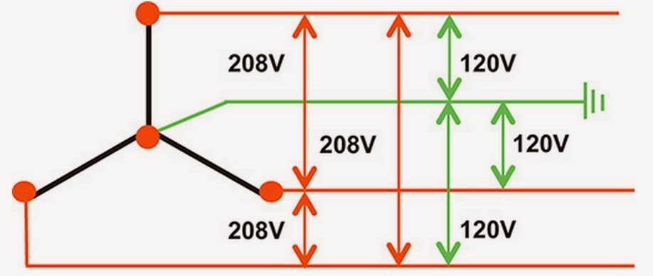
A balance 3-phase voltage can only be obtain if we have a 3-phase ac generator by converting potential energy to mechanical energy and to electrical energy in the hydro-power plant for example. A three-phase voltage may be arranged in delta (∆) or wye (Y) system. A wye system allows to provide two different voltages for example 173-300 volts, 173v is the line to neutral voltage and the 300v is the line-to-line voltage. In delta system can only provide one voltage magnitude however it has a greater redundancy as it may continue to operate normally with one of the three supply windings offline.


This is the graph of the balance three-phase voltage source connected into the loads by three to four wires and each voltage source has 120 degrees apart.


3-phase delta system


 3-phase wye system

Conversion of delta to wye and wye to delta source


VVL  /  sqr.(3)∠-30
VVp sqr.(3)∠30


Conversion of delta to wye and wye to delta loads


ZY=ZD / 3
ZD= ZY (3)


Balance Y-Y connection example problem


find the total current flowing in a single phase circuit (Ia)
Vy = 110∠0 V

since it is a balance single phase first we draw the single phase equivalent circuit


we know that
                                      Ia=Van / Zy
to obtain (Ia) we calculate the total impedance of the single phase circuit
                                      Ia=110∠0 / (5-j2)+(10+j8)
                                      Ia=6.81∠-21.8 A
the total current flowing in the 3-phase system is
                                     6.81A x 3 = 20.23 A

finding the delta equivalent of the source is
                                      VD =Vp sqr.(3)∠30
                                      VD = 110 sqr.(3) (0+30)
                                      V=190.5230
delta equivalent of the load in the circuit
                                       ZD= ZY (3)
                                       ZD=10+j8 x (3)
                                       ZD=30+j24 ohm
note: when the source is connected in delta it is much easier if we convert it in Y- connection to solve the problem.

Thursday, February 13, 2014

AC Power analysis

Apparent Power and Power Factor

Apparent power is a measure of alternating current (AC) power that is computed by multiplying the root-mean-square (rms) current by the root-mean-square voltage. 

it is the magnitude of a complex power S

The apparent power is measured by VA (volt ampere) it is also the product of the rms value.

in previous formula:

                                                      P = 1/2 Vm Im cos(θv - θi)

and

P = Vrms Irms cos(θv - θi) = S cos(θv - θi)

S = Vrms Irms

Power factor is define as the ratio of the real power flowing to the load, to the apparent power in the circuit.

                                                          pf = P/S = cos(θv - θi)

Example:

Obtain the power factor and the apparent power of a load whose impedance is Z=60+j40Ω  when the applied voltage is v(t) = 150 cos(377t + 10) V.


I = V/Z  = (150 ∠ 10)/(60 + j40 Ω) = 2.08 -23.69 A

S = Vrms Irms = (120/√2)(2.08/√2) = 156 VA

pf = cos(θv - θi) = cos(10 - (-23.69)) = 0.832


Complex Power

complex power defined as:

                                                                  S = P + jQ
where:

P = the real part and measured in watt (W)

Q = is the reactive power it is measured by volt-ampere reactive (VAR)

S = is the complex power measured by volt-ampere (VA)

Complex power can be calculated by multiplying the Vrms of a circuit by the complex conjugate of the total circuit current.

                                                                     S = VI*
example:
Z = 25 + j15Ω  = 29.15 30.69

I = Vrms/Z = 10/29.15 30.69 = 342.99 -30.964 mA = 
I* = 342.9930.964 mA

Therefore:

S = VI*
S = (100)(342.9930.964 mA)
S = 2.94 + j1.76 VA = 3.49 30.964 VA


This is the power triangle the expression for the complex power.

Friday, February 7, 2014

AC Power Analysis

Instantaneous and Average Power


          Instantaneous power is a power that absorb by a sigle element. It is also a value of power p at time t is equal to instantaneous voltage at time t times the instantaneous current at time t.

formula:


p(t) = v(t) i(t)

each  instantaneous voltage and current has its own formula:

v(t) = Vm cos(ωt + θ)
i(t) = Im cos(ωt + θ)

The Vm and the Im are the amplitudes or the peak values, and θv and θi are the phase angle of the element. 

So we arrive this formula:

                                             p(t) = v(t) i(t) = Vm Im cos (ωt θv) cos (ωt θi)

We apply the trigonometric identity.

cos A cos B = 1/2 [cos (A - B) + cos (A + B)]

and express Equation as:

                                  p(t) = 1/2 Vm Im cos(θv - θi) + 1/2 Vm Im cos (2ωt + θv + θi)


average power is the average power of an instantaneous power in a period.

formula given is:

                                                            P = 1/T ∫ p(t) dt

by substituting p(t) in the equation:

                        P = 1/T ∫ 1/2 Vm Im cos(θv - θi) dt  +  1/T ∫ 1/2 Vm Im cos(2ωt + θv + θi)dt

                        P = 1/2 Vm Im cos(θv - θi) 1/T dt + 1/2 Vm Im 1/T ∫ cos(2ωt + θv + θi) dt

The first integrand is constant and the average of the constant is the same. the second integrand is a sinusoid. The average of the sinusoid is over its period is 0 because the area under the sinusoid during a positive half cycle is canceled by the area under it during the following half cycle. th second tern will be vanished and the power becomes:

                                                     P = 1/2 Vm Im cos(θv - θi)

Example:

       A current I = 10∠30 A flows through an impedance Z = 20-22 Ω find the average power delivered to the impedance.

First we get the voltage across the impedance Z so we can solve the power delivered to the impedance.

                                   V = IZ = (10∠30 A)(20∠ -22 Ω) = 200∠ 8 V

since we have the required voltage so:

                                     P = 1/2 Vm Im cos(θv - θi)
                                     P = 1/2 (200)(10) cos(8 - 30)
                                     P = 1000 cos(8 - 30)
                                     P = 927.18 W


Maximum Average Power Transform

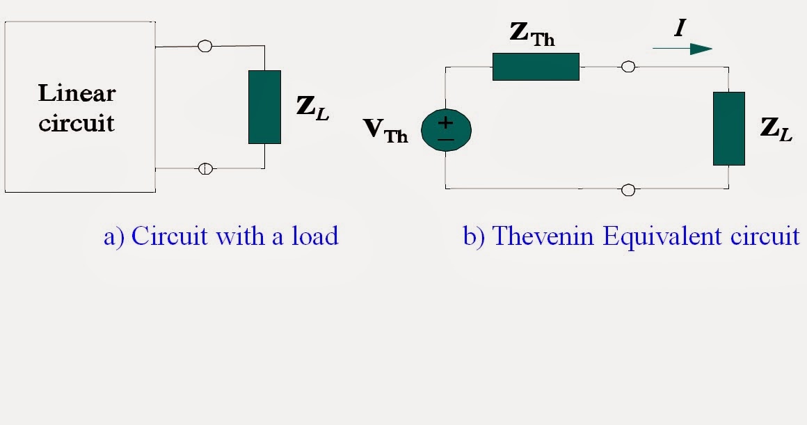
       The maximum power transfer theorem states that, to obtain maximum external power from a source with a finite internal resistance, the load impedance must equal to the complex conjugate of the thevenins impedance.

Finding the maximum average power which can be transferred from a linear circuit to a Load connected.


Load ZL represents any element that is absorbing the power generated by the circuit.

In rectangular form, the thevenin impedance ZTh and the load impedance ZL are:


Ajust RL and XL to get maximum P


Therefore: ZL = RTh - XTh = ZTh will generate the maximum power transfer.

Maximum power is:


For Maximum average power transfer to a load impedance ZL we must choose ZL as the complex conjugate of the Thevenin impedance ZTh


Saturday, January 11, 2014

thevenin and Northon theorem


Thevenin and Northon theorem


-Thevenin’s theorem  says that the linear two-terminal  circuit can be replaced by an equivalent circuit consist of voltage source Vth in series with a resistor Rth.

-It is a method for the reduction of a portion of a complex circuit into a simple one. this mean that the single voltage source and series resistor must behave identically to the actual network it is replacing.


steps:

          -We will turn of all independent sources and shorting the terminals of voltage source and open terminals in the current source and Rth or the Zth is the input impedance of the network between the terminal a and b.


           -By removing all independent source solve the total impedance in the terminal a and b to obtain the Rth or Zth and simply voltage division we can solve Vth but it depends on the scenario.


-Northon's theorem says that linear two-terminal circuit can be replace by an equivalent circuit consist of current source which is I n parallel with resistors.


-Replacing a network by its northon equivalent can simplify the analysis of a complex circuit. in this example, the northon current is obtained from the open circuit voltage (the thevenin voltage) divided by the resistance R. The resistance is the same in the thevenins resistance.


northon and thevenin equivalent formula:


                                Rn = Rth

                                I n = Vth/Rth
                                Vth = (I n) (R n)

Source transformation

Source transformation


Another method of solving and simplifying a circuit is source transformation. Transforming a current source to voltage source by replacing the position of the resistor or the impedance of a circuit and vice-versa. These transformations are useful for solving circuits. It will explain the importance of source transformation and it will explain how to use these conceptual tools for solving circuits.


By using simply the formula of ohm’s law we can transform the circuit

                                                 V=IZ         or        V=IR
                                                 I=V/Z        or        I=V/R


Sample problem:
                      find the current across R4


                     Equivalent circuit that we transform      
                                   by using source transformation:
                                             
                                     I=V/R1    I=50/25     I=2A


                      We can solve our I R4 by using current division.


                    The current flowing in I R4 = 0.2267